

Ever had that moment when you look at a classic car and think, ‘What if it could have the best of both worlds?’ Well, that’s exactly what we did with our ’55 Chevy Bel Air. I wanted to keep the vintage vibes intact while injecting some modern muscle into the ride, and what better way to do that than with a custom 4-link suspension?
To take that step we have decided to upgrade the diff to a much larger one ( more details in another project soon! ) , with upgrading the diff we thought that we could upgrade to a custom 4 link, this allows us to control the smoothness of ride a lot more as well as control launch to a higher degree of accuracy!
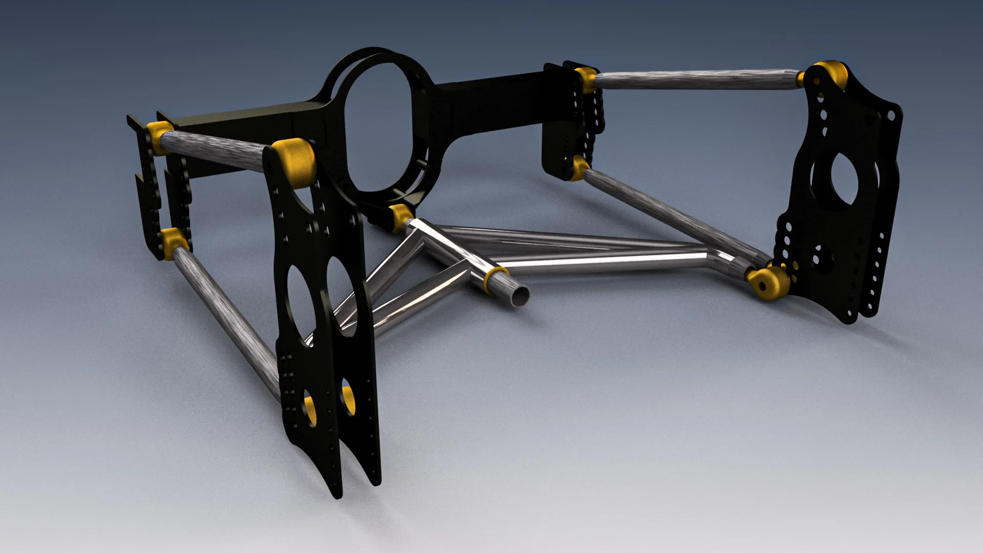
As an Engineer, I of course had to focus on the math behind a 4 link, typically a 4 link allows for the diff to move perpendicular to the road consistently in a parallel path, this is standard on a “Road car”, but this should not just be a road car, so I produced a CAD model that plotted out the distance between the center of gravity of the 55, as well as a few other key points.

As you can see in this cad model, I not only designed the links geometry but also designed the “wishbone” to change length with the appropriate range of motion of the diff, designed the mounted plates and a open cross brace to allow for the drive shaft through to be mounted into the diff.
This design used chromoly tube, as it was incredibly strong, allowing for the entire system to be lighter. Of course this is still not appropriate for a general street vehicle and is over kill, and with that in mind we made sure the rest of the system was equally bad-ass with laser cut 6mm plates and 1/2″ heim joints.
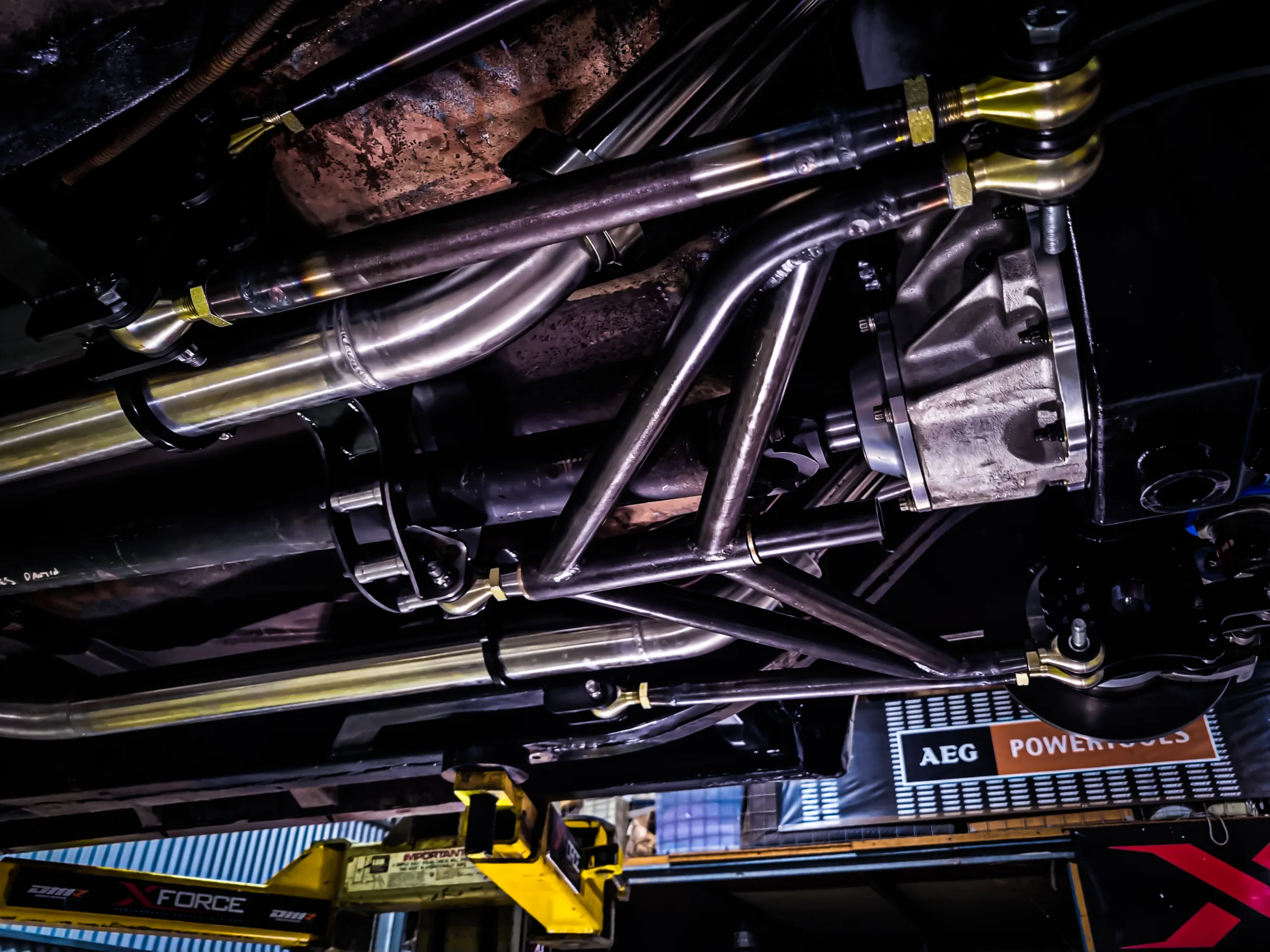
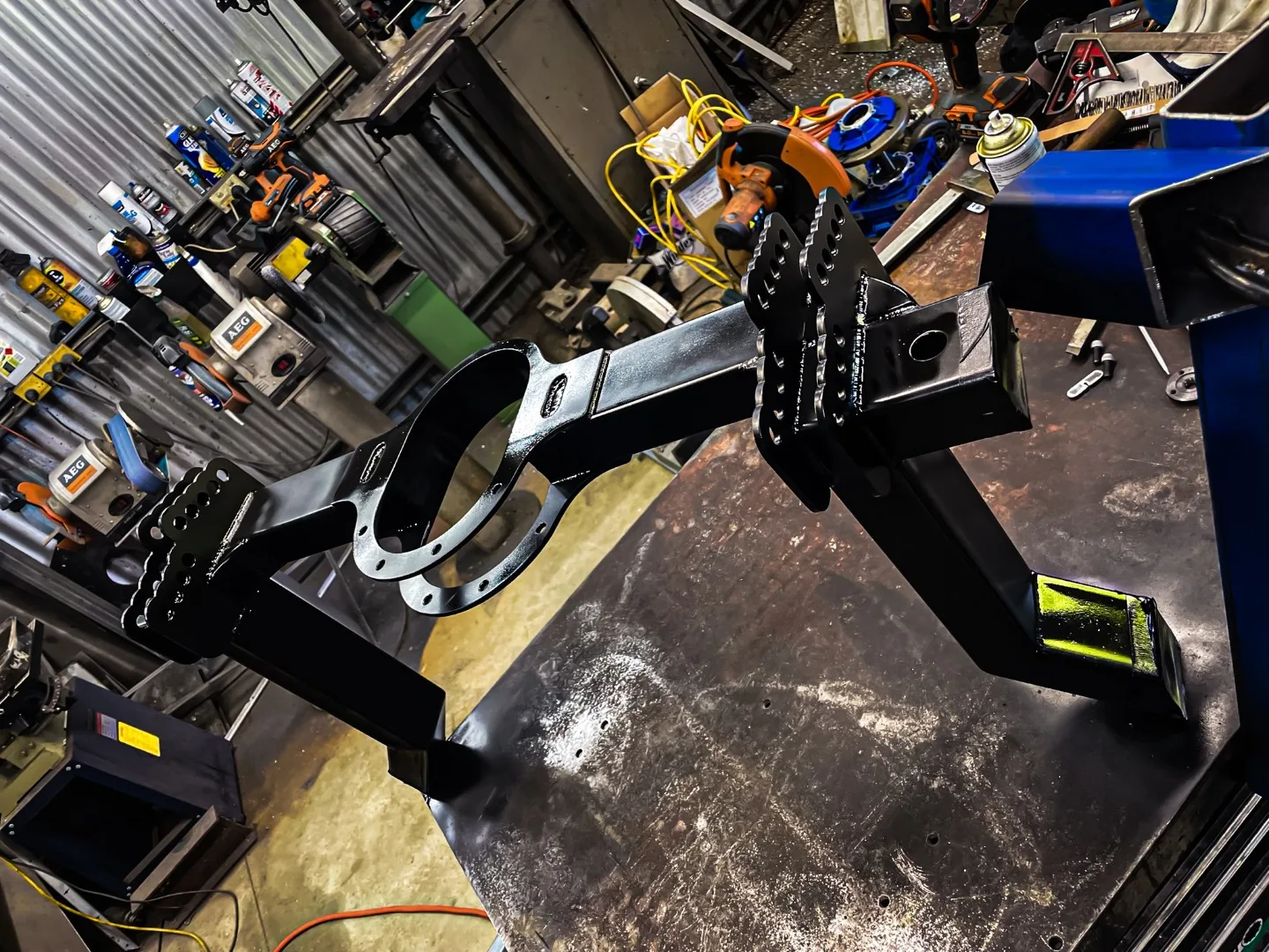
The manufacturing of this 4 link was fundamentally pretty simple given that the CAD model was accurate, the 4 link tubes were cut to length and capped with custom turned ends, these ends had a male section that fitted within the tube. with a TIG welded bead around that seam, although all the section was cut to length to match the CAD program but during manufacturing lengths can change, this can be a result of many different factors, but this is not an issue as the 4 link used threaded heim joints allowing length adjustments.
The Wishbone was designed all in cad so all angles were calculated before any cuts were made although sculpting the radius so that the tube would mate correctly was done by hand. In hind site and if we were to remake another system I would produce a 3D printed JIG to and uses a hole saw or a similar systems to make sure that this was perfect.
A sleeve was turned to make sure that a sliding fit was made between the center of the wishbone and the slide rod attached to the cross beam.
The total machining time, not counting any lead time (laser cut plates) or time spent in CAD resulted in approximately 1.5 work day, this really demonstrates the incredible strength of 3D modeling.
Unfortunately I did not take any images prior to mounting it to the car, but it looked great on there!

I’m pretty damn happy with the outcome of this project!
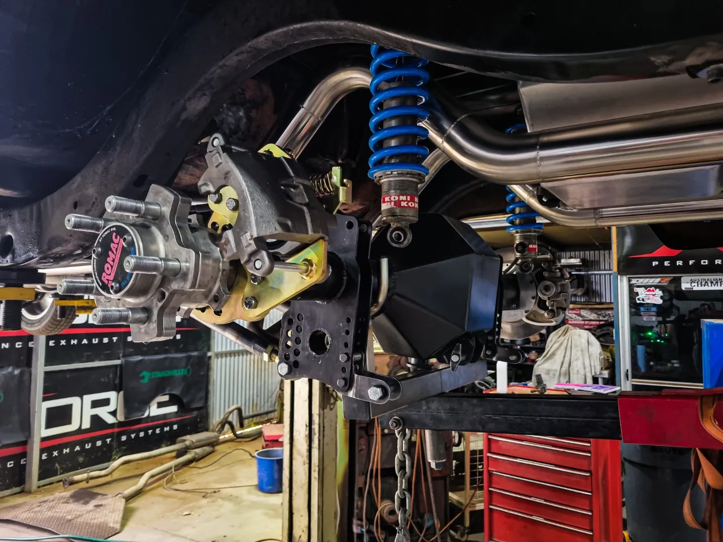
The laser cut plates and cross beam were welded into either the chassis or the differential and all fasteners uses were standard high grade bolts with 12 point nuts of course.

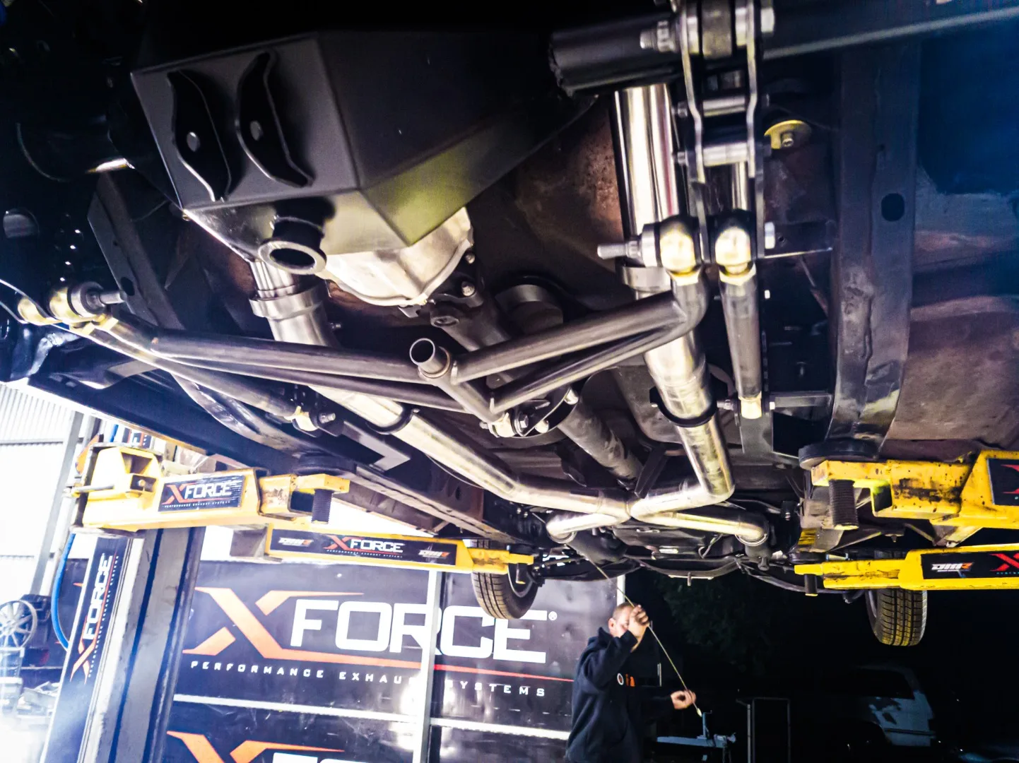
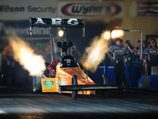
Landing on the ground, the 55 first test went great leaving black marks on the road behind it! The new diff had no issues and the 4 link performed exactly as it should!
minor adjusts could of been made to make sure its launch was a bit more efficient, but we may have to wait till we put an engine worth its quality in it.


One Response
test comment